Reverse Engineering Services That Will:

Improve Product Design

Extract design intent from existing parts with data gathering methods that are highly accurate and repeatable.

Create a Usable 3D Model

Get a simple-solid model or take it further to get a fully-parametric CAD model.

Re-Design Legacy Parts

No CAD data? No problem. Rebuild a parametric model from scratch or get all design tree information for editing.

Get A No-Obligation Quote to fully SEE Any Product

Our engineers are ready to help with your challenges. Send through some initial project details and we'll review and get back to you with a project estimate and additional questions.

Technologically Advanced, Experienced Backed

Delivering the Exact Reverse Engineering Services Your Project Requires

  • Re-design legacy parts
  • Rapid prototyping
  • 3D printing
  • Extract design intent
  • Create new molds
  • Re-create one-of-a-kind parts
  • 3D models for marketing or archiving
  • Product development

Ultra-precise, 3D Measuring to Reconstruct an Object into a 3D CAD Model

Our reverse engineering services are industry leading, but what does it take to build a 3D CAD model?

Step 1 – Measurement/Gathering Data

There are several methods that can be utilized for data extraction.

Some of these include:

  • CMM
  • Video measurement systems
  • Laser scanners

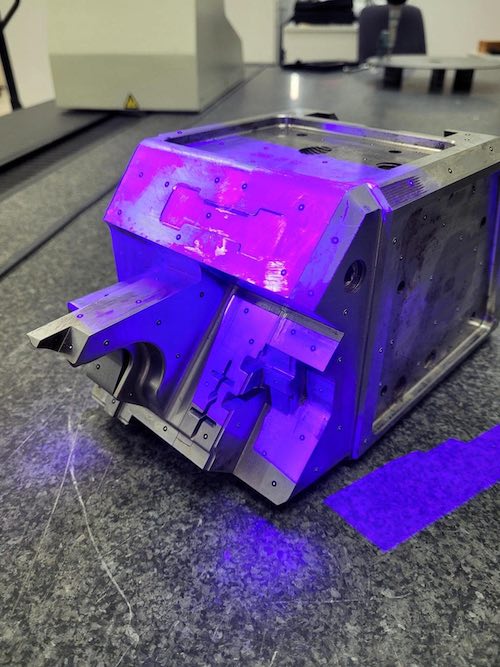
As the industry evolves, other cutting edge, extremely accurate systems are emerging. Industrial CT scanning and blue light scanning are two such technologies Nel PreTech has mastered.

Step 2 – Data Processing

This is typically a preprocessing step to get ready for the third step of creating a 3D CAD model. For others, this may be the final step. For customers interested in data analysis, or rapid prototyping with their own internal CAD department, this step may be all that is needed.

The raw data from step 1 is processed and used to create a polygonal .STL model. For those customers who require a solid .STEP conversion of the .STL data set, further mesh editing/processing of the .STL may be needed.

Step 3 – CAD Model Creation

Rapid Surfacing/quick-wrap method: As mentioned in step 2, the option to convert the polygonal .STL file to a solid .STEP file is available. This is typically the least costly and fastest method of creating a CAD model.

Our reverse engineering software takes the STL model from the previous step and shrink wraps a surface over the entire STL model. The result is a completely surfaced model that matches the scanned part exactly. All imperfections such as warp, parting lines, flash, etc. are captured.

The surfaced model can then be exported in an IGES or STEP format for further processing in other CAD software packages. This method produces a solid model that is a simple solid conversion of the polygonal .STL file. No parametric information is contained in the file.

Parametric CAD modeling

Data from step 1 and step 2 can be combined and used as design templates to rebuild a parametric model from scratch.

  • These parts contain geometrically perfect surfaces
  • They can be exported in a .STEP or .IGES format.

Fully parametric models can also be produced and provided in a native Solidworks format.

  • Models provided in this way contain all design tree information and can be edited within Solidworks.
  • These types of files are best suited for parts that are being re-designed or going through several different design iterations.
  • These files can also be used to generate blueprints within Solidworks.

Reverse Engineering Across ALL Industries

Serving more than 3,000 clients in a diverse mix of industries.
Medical Devices

Luers, Drug Delivery, Medical Implants, Dental Hardware, Medical Connectors

Automotive

Electric Vehicles, Batteries, Farming & Mining Equipment, Recreational Vehicles, Marine

Aerospace

Manifolds, Pumps, Nozzles, Electronics

Consumer Products

Packaging, Disposable Cutlery, Sporting Goods, Tech Manufacturing

Traditional Manufacturing

Die Casting, Metal Stamping, Plastic Injection Molding, Metal Injection Molding

Additive Manufacturing

3D Printing, Rapid Prototyping, Direct Manufacturing, Tooling

Defense

Firearms, Weapons Systems, Hypersonics, Ammunition

Key Updates on ISO 80369-7

Cutting-Edge Equipment
  • Ziess Metrotom 800
  • Zeiss Metrotom 1500
  • ATOS Q Blue Light Scanner
  • Mycrona Multi-Sensor Vision/CMM System
  • Unique Laboratory: Maintains 68°F ±0.5°F
    Maintains 45% humidity ±5% Controls dust particulate, light candelas, noise decibels, & air velocity.
  • Leading metrology software for precise examination & analysis of your manufactured products.
Multidisciplinary Team
  • Work with designers who are also metrologists.
  • Have confidence in a team that understands the uncertainties involved in data capture.
  • Expect complete accuracy every time because we know this is crucial to providing reverse-engineered CAD models & blueprints.
Accreditation

Establishes:

  • Competency of skill
  • Adequacy of equipment
  • Reliability of business process/quality management system
  • Contract review & final inspection
  • Proven measurement uncertainty
ISO/IEC 17025 Scope & Certificate
Cover of brochure showing an ATOS Q blue light scanner

Download our Reverse Engineering brochure to get started solving your challenges.

You'll find all the detailed service information you need in one brochure.

Download Brochure

Case Studies

Colormap of CT scan data within VG software
Challenge:

A manufacturer and supplier of industrial scale food processing blades needs to manufacture a part in the U.S. They need a 3D CAD model to work from.

Solution:

3D scan to cad using Geomagic Design X

Results:

Client gains a .step model which can be opened and read universally across all CAD/CAM software packages. They also save money by manufacturing the part in the U.S.

Sharp Results: 3D Modeling Cuts Like a Knife

Read Full Case Study
Industrial CT scanning services allows analysis of hidden elements
Challenge:

Major sporting goods manufacturer needs a CAD model built using scan data from an existing golf club.

Solution:

3D scanning and mesh editing in specialized CAD modeling software to remove features.

Results:

Client saves time with our quick turnaround and develops a new product with our accurate 3D SCAN TOCAD services.

A Big Hit: Product development expedited by 3d scanning golf club into CAD model

Read Full Case Study
Blue light scan of an automotive door handle
Challenge:

Global OEM medical device company needs help developing and launching drug delivery pumps.

Solution:

CT scanning and value-add services create a turnkey solution to give the client a competitive advantage.

Results:

20 new tools in 20 weeks.

A Medical Miracle: Drug delivery pumps developed and launched in record time with 3D scanning services.

Read the full Case Study

3D Scanning for Reverse Engineering

3d scanning is a technology used to collect a 3d data set of an object or part. The digitization process captures the exact size and shape of a part without need for cutting or destruction. The data is then used to construct a 3d model.
  • Surface variations can be analyzed with user-definable color patterns.
  • Cross sections give the ability to see otherwise hidden features.
  • Materials of different densities and surface finishes are a good fit for 3d scanning as well.

There are a variety of technologies used to acquire x, y, z coordinates of a real-world object. If you choose to work with Nel PreTech, you’ll find we employ the newest 3d scanning technologies. Talk to our experts to find the appropriate fit for your 3D scan to cad application.
X-ray image of a handgun.

Beyond Reverse Engineering

Reverse engineering services, part digitization, and 3D modeling are three fundamentally linked processes. To be able to provide services in any one, you must excel at all three. Here is the value-add we bring to your projects:
  • 30 years in business
  • In-depth knowledge of mathematics & ASME standards
  • Maintain, train, & contribute to development of industry's leading metrology, engineering, & 3d scanning software
  • Results in days to 1 week
  • Subject matter experts
  • Physicists & engineering physics graduates
  • Trusted consultants
  • Full attention of our resources
  • Questions answered within minutes/hours
  • Legal certification for compliance & protection to our clients
  • Deep understanding & management of measurement uncertainty
  • Quality assurance

Post-Scan Processing

  • The removal of errors from the mesh created by erroneous points or “noise” from the point cloud.
  • Gaps or irregularities in the mesh can also be detected and healed. This is the most important & time-consuming step in the surface wrapping process.
  • It is crucial to remove or fix all errors prior to surfacing to ensure that the final model does not contain undesirable irregularities or surface anomalies.
  • The model must also be water-tight or “manifold” before surfacing.
Post scan processing of 3D scan

Creating a Parametric Model

  • An .stl file is generated from the raw scan data.
  • The next step in the process is mesh editing. Mesh editing is not as crucial to the parametric modeling process as it is for a surface wrap.The mesh just needs to be clean enough to extract dimensional data for feature modeling.
  • Dimensions are extracted from the scan & parametric features are created
  • The result is a fully parametric solid model with feature design history that can be transferred over to most major CAD packages for further design editing or incorporation into an assembly.
  • The model can also be exported in a STEP or IGES format.
  • Using the accuracy analyzer allows the user to see areas of deviation. This is useful for finding areas that may need to be further processed or to expose areas where the original part may be worn.
STL point cloud data of a manufactured part.Parametric model of a manufactured part.

3D Scanning Output Options

Getting to know the customer, the part, and intended use of the 3d scan data we provide helps us determine the best delivery method for your objectives. To learn more about our 3d scanning deliverables read: Engineered Formats & Outputs for 3D Scanning Services.

Four Key Outputs:

  1. Raw data: A cloud of points. Sometimes a company may want this data for archival purposes or to test a tool over time to see if there is any wear.
  2. STL file: Polygon mesh
  3. Surface Wrap: Exact and true representation of the part “as is” in a .step file.
  4. Parametric Model: Builds perfect surfaces on top of an imperfect part or scan data.
3D scanning and reverse engineering a plastic clip

Additional Reverse Engineering Resources

Get More Out Of Your CT Scanning

Download the ultimate CT Scanning Buyer's Guide to improve understanding, time, and efficiency in your scanning needs. Over 50 Pages of useful data and case studies.

Download Now